Two Loop 160m Mag Antenna
I already own a small commercially made Mag loop (an Alpha - it is fine, it works ok, but it is small, and anything lower than 40m it is just out of it's comfort zone).
There is a UK ham called M0MSN who has an excellent you-tube channel, where he builds things (usually on his kitchen table).
This is what a normal loop looks like ..

Mike, a few years ago - he built a double loop. Which looks something like this...
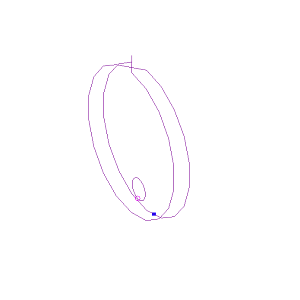
Why double ?
The 'maths' for mag loops suggests that the size needs to be 10-20% of the wavelength - for decent effiency. You could have a 1m diameter mag loop for 160m - it would not work very well.
If you want to check this yourself please look at the online calculator provided by https://www.66pacific.com/calculators/small-transmitting-loop-antenna-calculator.aspx.
So an efficient circumferance for 160m is between 19.7 and 39.3 meters at the specified frequency of 1.85 MHz.
Single Loop Effiency
Circumferance
- 20m
- 27% efficient
- 25m
- 42% efficient
- 30m
- 56% efficient
- 35m
- 66% efficient
- 39m
- 73% efficient
So bigger is better - but 39m Circumferance has a radium of 6.2m - so it would stand 12.4m tall !! This would be too difficult to support.
Two Loops - means smaller
It seems easy to suggest that therefore having two loops but with the same overall length(circumferance) should yield the same results ...
I tried to model this - but my NEC Primatives are not great when dealing with arcs and spirals.... So I resorted to programming.
I wrote a Double loop nec generator.
This is the code
from math import sin,cos
from pprint import pprint
DR=0.3  # Driven Radius
DR_EXTRA=0.333 # Raise Driven a little more
R=2.   # Radius
W=2.54*.825/100 #In Meters
SEG=1
ANGLE=20 # Steps in each circle
LOOPS=2 # How many concentric loops
DIST=0.3 #Cm between Loops
LIFT=5.0 # How much it is raised
wires=[]
driven=[]
cross_pos=-1
for l in range(0,LOOPS):
    for a in range(0,360,ANGLE):
        b=(a/360.0)*2.0*3.1415 #Radians
        x=sin(b)*R
        y=cos(b)*R
        d=l*DIST
        wires.append([x,d,y+LIFT])
        x=sin(b)*DR
        y=cos(b)*DR
        if (l==0):
            driven.append([x,DIST/2.0,y+LIFT-R+DR+DR_EXTRA])
    if l==1:
        cross_pos  = len(wires)
        print(f"CE Need to jump from wire {cross_pos} to {cross_pos+1}")
        print(f"CE We do this by going verticlly up a small gap.")
        print(f"CE In practice this could be more smooth")
tag=1
print("CM Double Loop build from Python")
print("CM")
print("""CE
CE
SY C=184.5434pf""")
for w in range(0,len(wires)-1):
    print(f"GW {tag:4d}\t{SEG:4d}\t{wires[w][0]:5.4}\t{wires[w][1]:5.4}\t{wires[w][2]:5.4}\t{wires[w+1][0]:5.4}\t{wires[w+1][1]:5.4}\t{wires[w+1][2]:5.4}\t{W}")
    tag=tag+1


w=0
tag=100
e=len(wires)-1
print(f"GW {tag:4d} {SEG:4d}    {wires[e][0]:5.4}   {wires[e][1]:5.4}   {wires[e][2]:5.4}   {wires[e][0]:5.4}   {wires[e][1]:5.4}        {wires[e][2]+0.2:5.4}  {W}")
tag +=1
print(f"GW {tag:4d} {SEG:4d}    {wires[w][0]:5.4}   {wires[w][1]:5.4}   {wires[w][2]:5.4}   {wires[e][0]:5.4}   {wires[e][1]:5.4}        {wires[e][2]+0.2:5.4}  {W}")


tag=200
for w in range(0,len(driven)-1):
    print(f"GW {tag:4d} {SEG:4d}    {driven[w][0]:5.4}  {driven[w][1]:5.4}  {driven[w][2]:5.4}  {driven[w+1][0]:5.4}    {driven[w+1][1]:5.4}    {driven[w+1][2]:5.4}    {W}")
    tag=tag+1
w+=1
print(f"GW {tag:4d} {SEG:4d}    {driven[w][0]:5.4}  {driven[w][1]:5.4}  {driven[w][2]:5.4}  {driven[0][0]:5.4}  {driven[0][1]:5.4}  {driven[0][2]:5.4}  {W}")

print("""GE 1
LD  0   27  1   1   0   0   C
GN  2   0   0   0   4   0.003
EK
EX      6       209     1       0       1       0       0       0
CE SET Freq to be a little up from bottom - so we can see how sharp this is
FR  0   0   0   0   1.84    0
EN""")
To run this - you need Python3 - which is usually installed on most machines these days.
To generate the NEC File you issue this command
python loop.py > 2L.nec
This will create a 2L.nec file - which you open using 4NEC2.
Analysing the NEC file
The model should build with only segment warnings from the driven loop - I do not know how to remove these. They are already 1 segment long.
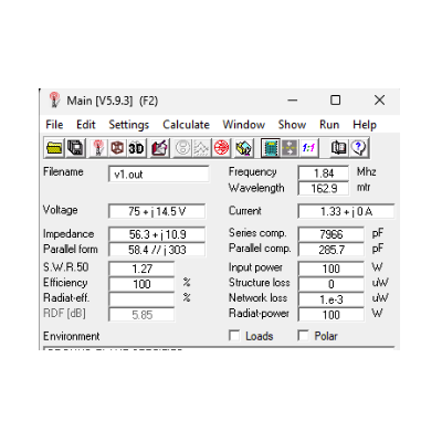
Nice SWR, and great looking effiency.
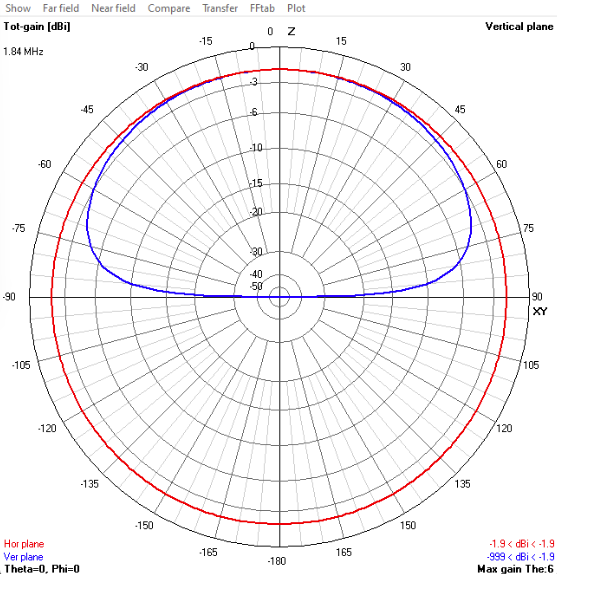
The far field plot looks good also - not the lowest angles.
I then did a frequency sweep from 1.78Mhz. - through to 1.9Mhz
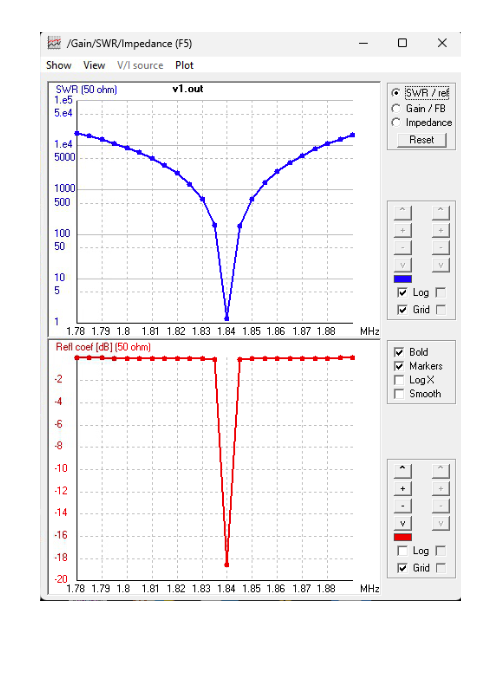
You will notice the VERY VERY sharp dip. This will be a blessing and a curse.
This will require re-tuning almost every time you move even the smallest frequency step. This will need to be automated (arduino Steppir anyone ?)
Parts list
- 25m of 7/8" Hard Heliax (Main Loop)
- 1.88m of LMR400 for driven Loop (Heliax will not bend this small)
- Some supports for the Heliax
- 184pF Variable Capacitor